You can know every new products be published here, and witness our growth and innovation.
Date:08-04-2021
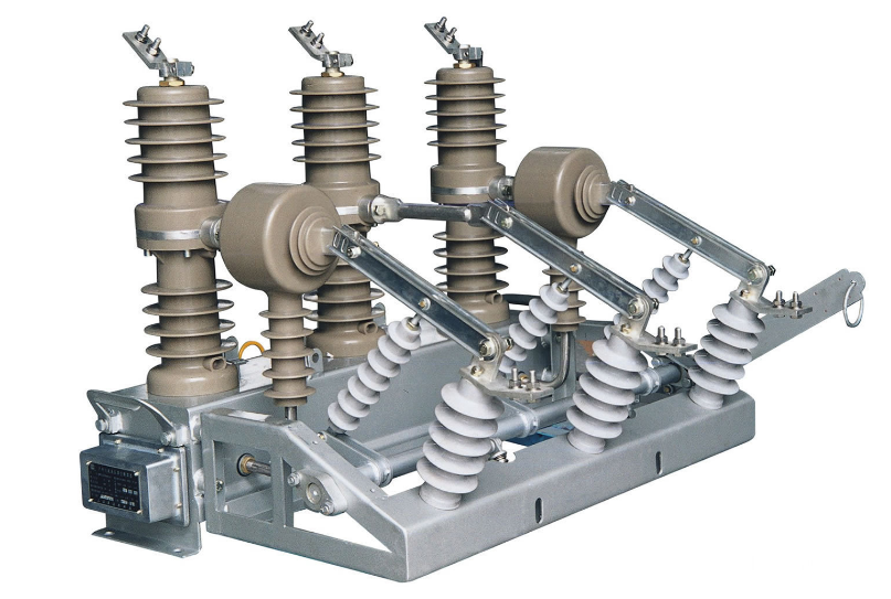
High voltage circuit breaker (or high voltage switch) is the main power control equipment of the substation, with arc extinguishing characteristics, when the normal operation of the system, it can cut off and through the line and various electrical equipment of no load and load current;When the fault occurs in the system, it and relay protection, can quickly cut off the fault current, to prevent expanding the scope of the accident.
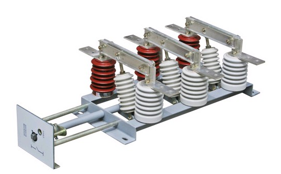
The disconnection switch does not have an arc extinguishing device. Although the regulations stipulate that it can be operated in the situation where the load current is less than 5A, it is generally not operated with load.However, the disconnecting switch has a simple structure, and its operating state can be seen at a glance from the appearance. There is an obvious disconnect point during maintenance.
Circuit breaker in use is referred to as “switch”, disconnecting switch in use is referred to as “knife brake”, the two are often used in combination.The differences between the high voltage circuit breaker and disconnecting switch are as follows:
1) The high voltage load switch can be broken with load, with self-extinguishing arc function, but its breaking capacity is very small and limited.
2) High voltage disconnecting switch is generally not with load breaking, there is no arc cover structure, there is also a high voltage disconnecting switch can break load, but the structure is different from the load switch, relatively simple.
3) High voltage load switch and high voltage disconnecting switch can form an obvious breaking point. Most high voltage circuit breakers do not have isolation function, and a few high voltage circuit breakers have isolation function.
4) The high voltage disconnecting switch does not have the protection function, the protection of the high voltage load switch is generally fuse protection, only quick break and over current.
5) The breaking capacity of high voltage circuit breakers can be very high in the manufacturing process.Mainly rely on the current transformer with secondary equipment to protect.Can have short circuit protection, overload protection, leakage protection and other functions.
Classification of switch operating mechanisms
1. Classification of switch operating mechanism
We now encounter the switch is generally divided into more oil (older models, now almost not seen), less oil (some user stations still), SF6, vacuum, GIS (combined electrical appliances) and other types.These are all about the arcing medium of the switch. For us secondary, closely related is the operating mechanism of the switch.
The mechanism type can be divided into electromagnetic operation mechanism (relatively old, generally in the oil or less oil circuit breaker is equipped with this);Spring operating mechanism (currently the most common, SF6, vacuum, GIS generally equipped with this mechanism);ABB recently introduced a new type of permanent magnet operator (such as VM1 vacuum circuit breaker).
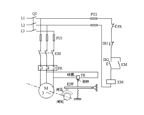
2. Electromagnetic operating mechanism
The electromagnetic operation mechanism completely relies on the electromagnetic suction generated by the closing current flowing through the closing coil to close and press the trip spring. The trip mainly relies on the trip spring to provide energy.
Therefore, this type of operation mechanism trip current is small, but the closing current is very large, instant can reach more than 100 amperes.
This is why the dc system of the substation should open and close the bus to control the bus.The closing mother provides the closing power, and the control mother supplies power to the control loop.
 The closing bus is directly hung on the battery pack, the closing voltage is the voltage of the battery pack (generally about 240V), the use of battery discharge effect to provide a large current when closing, and the voltage is very sharp when closing.And the control bus is through the silicon chain step-down and mother connected together (generally controlled at 220V), closing will not affect the stability of the control bus voltage.Because the closing current of the electromagnetic operating mechanism is very large, the protective closing circuit is not directly through the closing coil, but through the closing contactor.The trip circuit is directly connected to the trip coil.
Closing contactor coil is generally voltage type, resistance value is large (a few K).When the protection is coordinated with this circuit, attention should be paid to closing to keep the general start.But this is not a problem, trip maintains the TBJ can generally start, so the anti-jump function is still there.This type of mechanism has a long closing time (120ms~200ms) and a short opening time (60~80ms).
3. Spring operating mechanism
This type of mechanism is the most commonly used mechanism at present, its closing and opening rely on the spring to provide energy, the jump closing coil only provides energy to pull out the spring positioning pin, so the jump closing current is generally not large.Spring energy storage is compressed by the energy storage motor.
Spring energy storage operator secondary loop
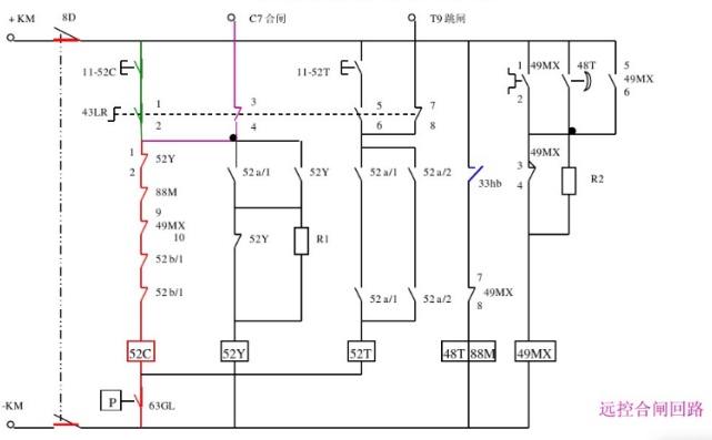
For the elastic operation mechanism, the closing bus mainly supplies power to the energy storage motor, and the current is not large, so there is not much difference between the closing bus and the controlling bus.Protection with its coordination, generally there is no special need to pay attention to the place.
4. Permanent magnet operator
The permanent magnet operator is a mechanism applied by ABB to the domestic market, first applied to its VM1 10kV vacuum circuit breaker.
Its principle is roughly similar to the electromagnetic type, the driving shaft is made of permanent magnet material, permanent magnet around the electromagnetic coil.
Under normal circumstances, the electromagnetic coil is not charged, when the switch to open or close, by changing the polarity of the coil using magnetic attraction or repulsion principle, drive open or close.
Although this current is not small, the switch is “stored” by a large capacity capacitor, which is discharged to provide a large current during operation.
The advantages of this mechanism are small size, less transmission mechanical parts, so the reliability is better than the elastic operation mechanism.
In conjunction with our protection device, our tripping loop drives a high-resistance solid-state relay that actually requires us to provide it with a pulse of action.
Therefore, the switch, keep the loop certainly can not be started, the protection of the jump will not be started (the mechanism itself with jump).
However, it should be noted that because of the high operating voltage of the solid-state relay, the conventional design TW negative is connected with the closing circuit, which will not cause the solid-state relay to operate, but it may cause the position relay to fail to start because of too much partial voltage.
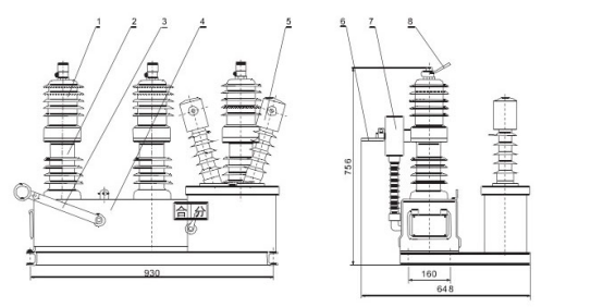
1. Upper insulation cylinder (with vacuum arc-extinguishing chamber)
2. Lower the insulation cylinder
3. Manual opening handle
4. Chassis (built-in permanent magnet operating mechanism)
Voltage transformer
6. Under the wire
7. Current transformer
8. On line
This situation encountered in the field, the specific analysis and processing process can be seen in the debugging case part of this paper, there are detailed descriptions.
There are also products of permanent magnet operation mechanism in China, but the quality has not been quite up to standard before. In recent years, the quality has been gradually brought to the market.Considering the cost, the domestic permanent magnet mechanism generally does not have capacitance, and the current is provided directly by the closing bus.
Our operating mechanism is driven by the on-off contactor (generally selected current type), hold and anti-jump generally can be started.
5.FS type “switch” and others
What we have mentioned above are circuit breakers (commonly known as switches), but we may encounter what users call FS switches in power plant construction.FS switch is actually short for load switch + fast fuse.
Because the switch is more expensive, this FS circuit is used to save costs.The normal current is removed by the load switch, and the fault current is removed by the quick fuse.
This kind of circuit is common in 6kV power plant system.Protection in conjunction with such a circuit is often required to prohibit tripping or to allow rapid fusible current removal by delay when the fault current is greater than the allowable breaking current of the load switch.Some power plant users may not wish to protect a holding loop.
Because of the poor quality of the switch, the auxiliary contact may not be in place, and once the keeping circuit is started, it must rely on the breaker auxiliary contact to open before returning, otherwise the jump closing current will be added to the jump closing coil until the coil burns out.
The jump closing coil is designed to be energized for a short time. If the current is added for a long time, it is easy to burn out.And we definitely want to have a holding loop, otherwise it’s very easy to burn the protective contacts.
Of course, if the field user insists, the holding loop can also be removed.Generally, the simple method is to cut off the line on the circuit board that keeps the normally open contact of the relay with the positive control female.
In the debugging site must pay attention to, if the switch on and off operation, the position indicator is off.(excluding the spring is not stored energy, in which case the panel shows the spring is not stored energy alarm) The control power must be turned off immediately to prevent burning the switch coil.This is a basic principle to keep in mind on the spot.


Address:No.27, Binhai South 3 road, Yueqing Economic Development Zone, Wenzhou City,Zhejiang Province,China.