You can know every new products be published here, and witness our growth and innovation.
Date:11-02-2026
A few years ago, a utility customer called us about a pad-mounted transformer that had failed on a mild spring afternoon. No lightning, no short circuit, no visible fault. The post-mortem told a familiar story: months of sustained overload had slowly cooked the insulating fluid, degraded the paper insulation, and eventually carbonized the windings. The current had never once exceeded the threshold of a conventional fuse. The protection system did exactly what it was designed to do — and the transformer died anyway.
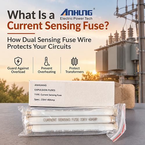
That failure mode is more common than most people think, and it’s precisely the gap that a current sensing fuse — and more specifically, dual sensing fuse wire — is designed to close.
A current sensing fuse is a protective element engineered to detect and interrupt abnormal current conditions on a circuit — secondary faults, excessive overloads, and low-side transformer faults in particular. In distribution equipment it typically sits inside a Bay-O-Net fuse assembly on the high-voltage side of an oil-immersed transformer. When fault current pushes the element past its designed melting point, the fuse opens and isolates the failed apparatus before the problem propagates upstream.
Simple enough. The trouble is that current alone doesn’t tell the whole story of how transformers fail.
Industry experience — and utility failure statistics generally — points to thermal aging as one of the leading causes of distribution transformer failure. A unit can run for months at 110% or 120% of nameplate load without ever triggering a current-only fuse, while its fluid temperature climbs steadily and its insulation life drains away. IEEE loading guides are blunt about the math: insulation aging roughly doubles for every 6–8 °C rise above rated hotspot temperature. By the time the overload becomes a hard fault, the transformer is often already a write-off.
This is where the “dual” in dual sensing fuse wire earns its keep. The fuse element responds not only to fault current but also to the temperature of the surrounding transformer fluid. Push the fluid past a safe threshold — through overload, a failed radiator, or a brutal heatwave — and the fuse operates before the insulation pays the price. In effect, it protects against the two failure mechanisms that actually kill transformers in the field, not just the one that’s easiest to detect.
In practice, we rarely recommend the dual sensing fuse wire as a standalone device. The standard arrangement — and the one most North American pad-mount specifications call for — is a two-fuse scheme. The Bay-O-Net fuse link handles secondary faults and overloads, while a series-connected current-limiting backup fuse (an ELSP type) takes care of high-magnitude short circuits. The two are coordinated so the backup fuse only sees action during genuine internal equipment failure. Between them, they cover the full fault spectrum, from a modest sustained overload to the maximum available short-circuit current.
One detail worth mentioning, because it trips people up during coordination studies: the time-current curves of the Bay-O-Net link and the backup fuse must overlap correctly across the transition zone. We’ve seen more than one retrofit fail acceptance testing because someone paired a fuse link with a backup fuse rated for a different interrupting class. Get the coordination curves from the manufacturer and check them against your transformer’s through-fault withstand curve — it takes an afternoon and saves a very awkward commissioning meeting.
Ratings for dual sensing fuse wire in the AH SMRS class typically run from 6.3 A up to 140 A continuous, across 8.3 kV, 15.5 kV, and 23 kV voltage classes, with single-phase interrupting ratings reaching 3,000–3,500 A depending on whether the assembly is cover- or sidewall-mounted. Beyond the nameplate numbers, pay attention to construction. A PTFE tube housing, for instance, provides a track-free bore that holds full-rated voltage after operation — a detail that sounds minor until you’re the one explaining a restrike failure to a customer.
Also worth asking: is the fuse wire field-replaceable? It should be. Swapping a fuse link during a maintenance visit is a ten-minute job; replacing a sealed assembly is a truck roll, an outage window, and a procurement lead time.
Transformers rarely fail the way textbooks say they will. They fail slowly, thermally, and expensively — often while every conventional protective device on the pole sees nothing wrong. Dual sensing fuse wire addresses that blind spot directly, and in our experience it’s one of the cheapest reliability upgrades available on a distribution transformer.
If you’re working through a protection specification and want a second set of eyes on the coordination, our engineers are happy to walk through the curves with you — no obligation attached.


Address:No.27, Binhai South 3 road, Yueqing Economic Development Zone, Wenzhou City,Zhejiang Province,China.