You can know every new products be published here, and witness our growth and innovation.
Date:10-27-2026
In underground power distribution, a cable connector does much more than join a cable to a bushing. Its design affects how a circuit is switched, how equipment is maintained, and how easily a network can be expanded later. Two products often come up during specification: the T deadbreak connector and the loadbreak elbow connector.
They may both have a molded rubber body and a familiar separable-connection format, but they are built for different operating duties. Confusing the two can lead to an unsuitable cable accessory being specified for the job. Here is a practical look at where each one fits.
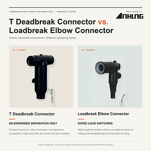
A T deadbreak connector, often called a deadbreak T-body connector, is used to terminate or splice underground cables connected to equipment such as transformers and switchgear. Its T-shaped body provides two horizontal interfaces and a vertical cable entrance, making it useful where more than one connection is needed at the same apparatus bushing.
The word deadbreak describes its intended operating condition: it must be connected or disconnected only after the circuit has been de-energized and confirmed safe by qualified personnel. It is not designed to interrupt load current.
The example shown here is a 35kV class, 600/900A deadbreak T-body connector. Its construction includes a peroxide-cured EPDM body, an insulating layer, a conductive shield, integrated stress control, a compression/mechanical lug, and a capacitive test point. The design is fully shielded and submersible and is stated to meet IEEE Standard 386. Depending on the selected version, the ordering table covers conductor cross-sections from 25mm² to 630mm².
A loadbreak elbow connector is a right-angle, plug-in termination commonly used to connect underground cable to pad-mounted transformers, switchgear, junction boxes, and other apparatus fitted with compatible loadbreak bushings.
Its defining feature is the ability to make and break specified load current when operated with the correct tool and procedure by trained personnel. It is not a substitute for a circuit breaker and is not intended to interrupt short-circuit current.
The elbow body typically includes EPDM insulation, a semi-conductive shield, a reinforced pulling eye, a cable lug, and an arc-ablative loadbreak probe. A test point may also be provided for use with suitable voltage or fault-indicating equipment.
The product shown is a 15kV, 200A loadbreak elbow connector, with an available cable conductor range of 35–150mm². Its loadbreak probe uses a tin-plated copper contact and an arc-ablative tip, while the stainless-steel reinforced pulling eye supports hot-stick operation.
| Comparison | T Deadbreak Connector | Loadbreak Elbow Connector |
| Operating duty | Connect or disconnect only on a de-energized circuit | Designed to make and break rated load current under specified conditions |
| Typical shape | T-shaped body with two horizontal interfaces | Right-angle elbow body |
| Current class | Commonly used in higher continuous-current applications; the example shown is 600/900A | Often used in 200A-class distribution systems; the example shown is 200A |
| Switching components | No loadbreak switching function | Loadbreak probe and arc-ablative contact design |
| Common use | Cable termination, splicing, and multi-way apparatus connections | Plug-in cable termination where routine load switching or sectionalizing is required |
| Connection planning | Useful for adding taps, splices, surge arresters, or another apparatus connection with suitable mating components | Usually provides one right-angle cable-to-bushing connection; system configuration depends on the apparatus and mating parts |
| Operation | De-energize, isolate, ground as required, and follow the approved procedure | Operate with the specified insulated tool and approved loadbreak procedure |
These are design distinctions, not a universal sizing rule. Always check the exact product datasheet, voltage class, continuous-current rating, cable range, bushing interface, and applicable standard.
A deadbreak T-body is a sensible choice when the connection will remain in place during normal service and disconnection will only take place after isolation. It is especially useful for higher-current feeders and installations where the T configuration helps with splicing or additional apparatus connections.
For example, a 35kV underground feeder terminating at switchgear may call for a 600A or 900A-class deadbreak system rather than a 200A elbow. The final selection still depends on the complete interface and the ratings of the connected equipment.
A loadbreak elbow is intended for distribution points where authorized crews need to connect or disconnect a cable under specified load conditions. Its compact right-angle form also suits the front of many pad-mounted transformers and other deadfront equipment.
This capability applies only within the product’s ratings and operating instructions. A loadbreak elbow must never be treated as a fault-interrupting device.
Two connectors can look similar in a catalog and still belong to different electrical systems. Before placing an order, confirm:
System voltage and the connector’s voltage class
Continuous-current and short-time-current requirements
Conductor material and cross-section
Diameter over cable insulation, not conductor size alone
Bushing interface and mating-component compatibility
Deadbreak or loadbreak operating duty
Test-point requirements
Installation environment, including submersion or outdoor exposure
Applicable IEEE, IEC, or project-specific standards
Cable insulation diameter is particularly important. Selecting a connector only by conductor cross-section can result in an incorrect adapter or housing size.
The simplest distinction is this: a deadbreak T-body is for de-energized connection work, while a loadbreak elbow is designed for rated load switching. The T-body is often associated with higher-current and multi-connection arrangements; the elbow is valued for compact, operable terminations on distribution equipment.
Neither is automatically the better product. The right choice is the one that matches the circuit, the bushing, the cable, and the way the installation will actually be operated.
If you are comparing connectors for a new project or replacement order, send us your system voltage, current rating, cable insulation diameter, conductor size, and bushing details. Our team can help you check the appropriate connector configuration and ordering information.
All installation, removal, and switching work must be carried out by qualified personnel in accordance with local safety rules and the manufacturer’s instructions.


Address:No.27, Binhai South 3 road, Yueqing Economic Development Zone, Wenzhou City,Zhejiang Province,China.