You can know every new products be published here, and witness our growth and innovation.
Date:09-28-2021
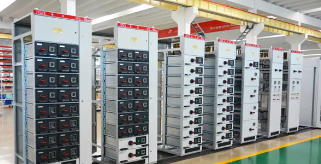
Switchgear refers to a complete set of power distribution devices assembled from primary equipment and secondary equipment according to a certain plan, which is mainly used to control and protect circuits and equipment. Switchgear can be divided into high voltage switchgear (fixed type and handcart type) and low voltage switchgear (fixed type and drawer type) according to the voltage levels of incoming and outgoing lines.
The structure of the high-voltage switchgear is roughly similar, mainly divided into the busbar room, the circuit breaker room, the secondary control room (instrument room), and the feeder room. There is generally a steel plate isolation between each room. Low-voltage switchgear is mainly classified according to the installation method of the components.
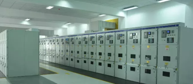
KYN28A-12 armored middle-mounted high-voltage switchgear
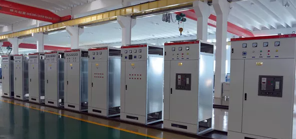
GGD low voltage fixed switch cabinet
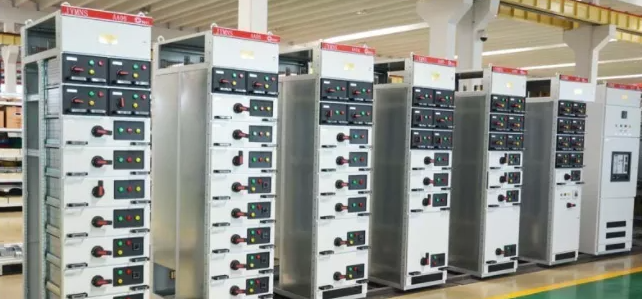
MNS low voltage draw-out switch cabinet
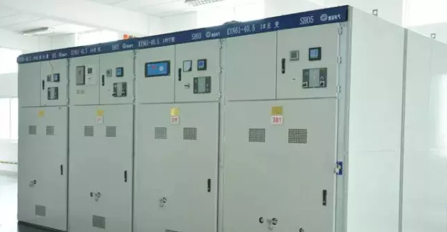
KYN61-40.5 Armored Removable Metal Enclosed Switchgear
GCK low voltage draw-out switch cabinet
Internal components include: bus (busbar), circuit breaker, conventional relay, integrated relay protection device, measuring instrument, isolating knife, indicator light, grounding knife, etc.
1. The incoming line cabinet is also called the power receiving cabinet. It is a device used to receive electrical energy from the power grid (from incoming line to busbar). It is generally equipped with circuit breakers, CTs, PTs, isolating knives and other components.
2. Outgoing cabinets are also called feeder cabinets or power distribution cabinets. They are equipment used to distribute electrical energy (from the bus to each outgoing line), and are generally equipped with circuit breakers, CTs, PTs, isolating knives and other components.
3. Bus connection
It is also called a bus breaker cabinet. It is a device used to connect two bus sections (from bus to bus). Bus connection is often used in single bus section and double bus systems to meet the requirements or guarantees of users for choosing different operating modes. Selective load removal in case of failure.
4. The PT cabinet voltage transformer cabinet is generally installed directly on the busbar to detect the busbar voltage and realize the protection function. Mainly install voltage transformer PT, isolating knife, fuse and arrester etc. inside.
5. The isolation cabinet is used to isolate the busbars at both ends or to isolate the power receiving equipment from the power supply equipment. It can provide a visible end point for the operator to facilitate maintenance and repair operations. Since the isolation cabinet does not have the ability to break and switch on the load current, the handcart of the isolation cabinet cannot be pushed or pulled when the circuit breaker matched with it is closed. In general applications, it is necessary to set the interlock between the auxiliary contact of the circuit breaker and the isolated handcart to prevent misoperation by the operator.
6. The capacitor cabinet is also called the compensation cabinet, which is used to improve the power factor of the power grid, or for reactive power compensation. The main components are groups of capacitor banks, switching control loops and fuses connected in parallel. Protect electrical appliances. Generally installed in parallel with the incoming cabinet, one or more capacitor cabinets can be operated in parallel. After the capacitor cabinet is disconnected from the power grid, because the capacitor bank takes a while to complete the discharge process, it is not possible to directly touch the components in the cabinet, especially the capacitor bank; within a certain period of time after the power is off (according to the capacitor bank It depends on the capacity, such as: 1 minute), re-closing is not allowed to avoid over-voltage damage to the capacitor. When performing automatic control functions, pay attention to the reasonable allocation of the switching times of each group of capacitor banks to avoid damage to one group of capacitors while other groups rarely switch on and off.
7. Measuring cabinet
Mainly used for measuring electric energy (kWh), and divided into high voltage and low voltage, generally installed with isolating switch, fuse, CT, PT, active watt-hour meter (traditional meter or digital meter), reactive watt-hour Meters, relays, and some other auxiliary secondary equipment (such as load monitors, etc.).
8. GIS cabinet is also called enclosed combined electrical cabinet, which is a closed combination of circuit breakers, isolating switches, grounding switches, CT, PT, arresters, busbars, etc. in a metal shell, and then a gas with good insulation and arc extinguishing performance (Sulfur hexafluoride SF6 is generally used) as an insulation measure between phases and ground, suitable for high-voltage and high-capacity power grids, used for power distribution and control.
9. When the circuit breaker is working normally, the circuit breaker is in the closed state (except for special applications), and the circuit is connected. When performing automatic control or protection control operations, the circuit breaker can be operated under the control of the comprehensive protection device to break or connect the circuit. The circuit breaker can not only switch on and off the normal load current, but also withstand a short-circuit current for a certain period of time (several or even tens of times the normal working current), break the short-circuit current, and cut off faulty circuits and equipment. Therefore, the main function of the circuit breaker is to break and make the circuit (including breaking and making the normal current, breaking the short-circuit current). Because in the process of breaking and closing the circuit, an arc is inevitably generated between the moving contact and the static contact of the circuit breaker. In order to protect the contacts, reduce the loss of contact materials and reliably break the circuit, measures must be taken to extinguish the arc as soon as possible. One of them is to use different arc extinguishing media to fill the dynamic and static contacts of the circuit breaker. According to the different arc extinguishing media, circuit breakers can be divided into: oil circuit breakers (more oil, less oil), sulfur hexafluoride (SF6) circuit breakers, vacuum circuit breakers, air circuit breakers, etc. The main primary equipment in the high and low voltage switchgear that we often come into contact with in the project is the circuit breaker. Since the moving and static contacts of the circuit breaker are generally wrapped in a container filled with arc extinguishing medium, the opening and closing status of the circuit breaker cannot be judged directly, usually through auxiliary devices of the circuit breaker (such as opening and closing position pointers). Etc.) to judge.
10. Isolation knife
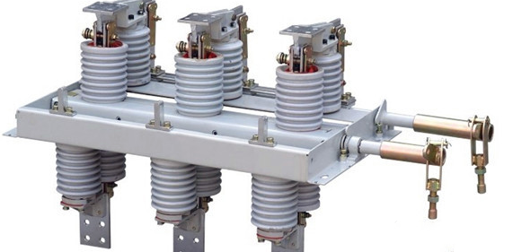
Isolation knife (or isolating switch) can identify the connection or disconnection because of the obvious fracture. It is mainly used to isolate the high-voltage power supply to ensure the safe maintenance of lines and equipment. The current that can be disconnected is very small (usually only a few amperes). ). Since there is no special arc extinguishing device, it cannot be used to break fault current and normal working current, and it is not allowed to carry out breaking operation with load.
11. Fuse
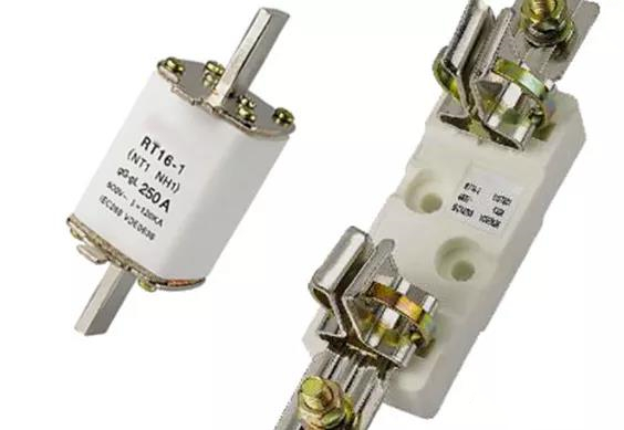
A fuse is a simple circuit protection electrical appliance. Its principle is that when the current flowing through the fuse reaches or exceeds a certain value for a certain period of time, its own melt melts and cuts off the circuit. Its action principle is simple, easy to install, generally not used alone, mainly used to cooperate with other electrical appliances. Main action characteristics: First, the current must reach a certain value, which has been made before the fuse leaves the factory and cannot be changed; second, a certain time must pass after the current reaches a certain value, which is also made by the manufacturer and cannot be changed. But there are many types, including delayed action, fast action, ultra-fast action, etc.; the third is that the body is damaged after action and cannot be reused and must be replaced; whether the fuse is blown can be judged by the fuse indicator or the appearance of the melt ; Commonly used fuses and insurance tubes belong to this category of electrical appliances.
12. Load switch
The load switch has a simple arc extinguishing device. The arc extinguishing medium is generally air, which can connect and break certain currents and overcurrents, but cannot break short-circuit currents and cannot be used to cut short-circuit faults. Therefore, it is absolutely not allowed to simply use a load switch to replace a circuit breaker; if a load switch is to be used, it must be used in conjunction with the aforementioned high-voltage fuse (in fact, fuse and load switch are often used in series for simple overload protection , In order to reduce the project cost). The load switch is similar to the isolating knife, and there is an obvious disconnection gap, and it can be easily judged whether the circuit is in the on or off state.
13. Transformer
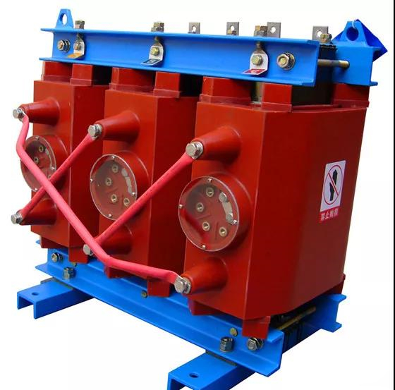
Simply put, a transformer is a device that uses alternating electromagnetic fields to achieve conversion of different voltage levels (actually the conversion of electrical energy), and the voltage before and after the conversion does not change in frequency. According to its use, it can be divided into many kinds, such as power transformers, rectifier transformers, voltage regulators, isolation transformers, and CT, PT, etc. What we often encounter at the project site is a power transformer.
Some of the main technical parameters related to the transformer include: ①Rated capacity: refers to the rated output capacity of the transformer under rated working conditions (equal to U×I, in KVA); ②Rated voltage: no-load, rated tapping, terminal voltage ③No-load loss: Under no-load condition, the loss of the transformer (also called iron loss); ④No-load current: Under no-load condition, the current flowing through the primary side coil Value; ⑤Short-circuit loss: the loss caused by the rated current on the primary side and the secondary short-circuit (mainly caused by the coil resistance); ⑥The concept of tapping (tap): In order to meet the needs of power grid operation, the high-voltage side of the general transformer There are taps, and the voltage values of these taps are expressed as a percentage of the rated voltage, the so-called tap voltage. For example, a high-voltage 10KV transformer has a ±5% tap, which means that the transformer can operate at three voltage levels: 10.5KV (+5%), 10KV (rated), 9.5KV (-5%). Generally speaking, the number of taps (tap points) of the on-load tapping transformer is more, such as 7 taps (±3×2.5%) and 9 taps (±4×2%). Since the synchronous switching of the tap changer cannot be fully guaranteed, the on-load tapping transformers generally cannot be operated in parallel. ⑦ Active load: the load that generates machine energy or heat energy in the power system. But the purely resistive load in the load only consumes active power, such as electric heating, electric furnace, lighting and other electrical loads are completely active loads. The load of asynchronous motors and synchronous motors consumes both active power and reactive power. Among them, the part that generates machine energy by work is an active load. The active load shall be supplied by the active power of the generator. ⑧Reactive power load: the part of the electric load that does not do work. Reactive power is consumed only in inductive loads. Such as: transformers, motors, air conditioners, refrigerators, etc. So while the generator outputs active power, it also needs to provide reactive power. When the reactive power cannot meet the grid, the voltage of the system will drop. In order to meet the needs of users, a reactive power compensator must be installed in the substation to maintain the balance of reactive power so that the voltage level can be maintained. ⑨ Accident reserve: one of the components of the reserve capacity in the power system. As the power generation equipment may have temporary or permanent failures that affect the power supply, the system must be equipped with a certain number of accidental backup power sources to ensure the safety of the power facilities. ⑩System disassembly: In order to prevent the system from losing step and the accident expansion, it will be complete The power system is broken down into several independent systems that no longer operate synchronously. Some local systems may suffer from power shortage after de-loading, and the frequency and voltage drop, so part of the load needs to be removed to prevent the stability of the entire system from being damaged.


Address:No.27, Binhai South 3 road, Yueqing Economic Development Zone, Wenzhou City,Zhejiang Province,China.