You can know every new products be published here, and witness our growth and innovation.
Date:08-27-2021
Fully insulated sulfur hexafluoride closed switch equipment also known as inflatable cabinet, common units are
Unit C: load switch module, equivalent to the incoming line of ring network cabinet.
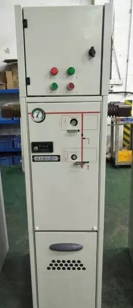
V unit: vacuum switch module, equivalent to circuit breaker unit.
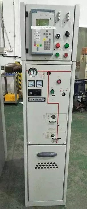
F unit: load switch fuse combination module, equivalent to the ring network cabinet outlet.
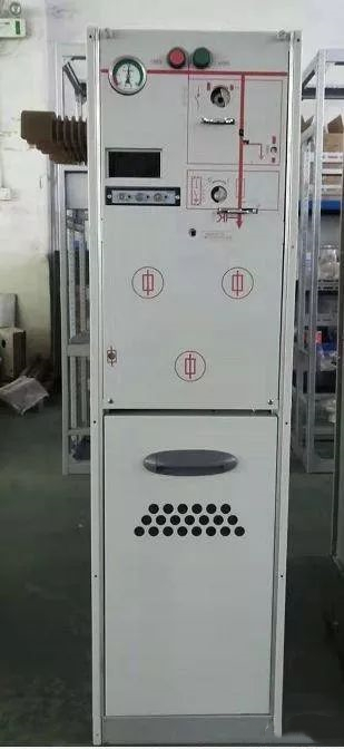
Unit D: cable connection module without grounding knife, equivalent to bus lifting cabinet.
One, live display circuit
Fault one: the three-phase electric display lamp does not light
Troubleshooting: 1. Whether the switch is closed.
Such as: if the power supply is only sent into the line cabinet, then only into the line cabinet unit is charged, other units do not switch is not charged, so in addition to the line cabinet other units charged display lamp is not bright.
2. Whether the secondary line is firmly connected.
Some problems tend to occur in small details, so we should judge the problem from simplicity to depth first.
3. Whether the sensor capacity matches the capacity of the live display, and whether the selected model is applied to the voltage level.
Fault two: live display three-phase phase deficiency
Troubleshooting: 1. A wire is damaged and grounded.
2. The wire is not securely connected.
Fault three: live display flashing in a case of no voltage
Troubleshooting: 1. First use an electrodetector to verify that there is no voltage on the primary side.
2, the interference of external power supply, if the charged display in the anti-interference this piece is not good, this piece is unavoidable.
You are advised to change the manufacturer and purchase products with strong anti-interference capability.
But xiaobian in this piece can tell you, if you choose a Q type with locked charged display, do not prevent the node into the charged display into the N line, if it is phase line of the charged display will be bright, if it is N line of the charged display is not bright (personal experience)
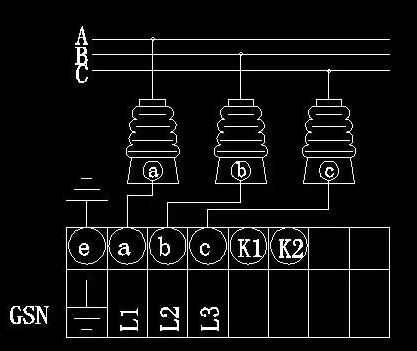
Two,Measuring circuit of current and voltage transformer
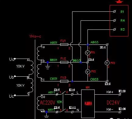
Transformer is a special transformer which can change high voltage into low voltage or high current into small current. It is mainly used for measuring instrument and relay protection device.
The operation and maintenance of transformer directly affect the accuracy of measurement in power system, the reliability of protection device operation and the safety of power grid, equipment and human body.
I. Common faults and treatment:
1. Emergency shutdown of the voltage transformer (current transformer) should occur under the following circumstances
(1) serious fever, smoke, oil.
(2) The high-voltage side fuse of the voltage transformer is fused twice in a row.
(3) Shell rupture, serious oil leakage.
(4) Internal discharge sound or abnormal sound.
(5) The equipment is on fire.
The handling method when the voltage transformer is smoking or on fire: if the fuse on the primary side is never fused before the smoke is emitted, and the fuse on the secondary side is fused for many times, and the smoke is not serious and has no insulation damage characteristic, and the fuse on the primary side is not fused when the smoke is emitted, the smoke should be judged to be caused by short circuit between the phases of the secondary winding (turns).
Before the secondary winding smoke without affecting the primary insulation damage, immediately exit the relevant protection and automatic device, take off the secondary side fuse, pull the primary focus isolation switch, stop the voltage transformer.
For oil filled type voltage transformer, if a lot of smoke, and with a strong odor, abnormal noise, to the voltage transformer internal winding with shells or lead between the shell and spark discharge, smoking the last side fuse fusing of 2 ~ 3 inferior phenomenon, should be judged as a bilateral insulation damage and smoking, so busbar voltage transformer, bus stop way stop using voltage transformer,
At this time, the voltage transformer can never be stopped by pulling the disconnecting switch, because the disconnecting switch has no arc-extinguishing ability. If the disconnecting switch is used to cut off the fault, the bus may be short-circuited, resulting in equipment damage or personal accident.
When the voltage transformer is on fire, the power supply should be disconnected immediately, the faulty voltage transformer should be isolated, and dry fire extinguisher or sand should be used to extinguish the fire.
2. The secondary circuit of the voltage transformer is disconnected
Phenomenon feedback:
(1) Three-phase voltage is unbalanced, the fault phase voltage is displayed as zero, and the watt-hour meter is displayed as abnormal
(2) The corresponding indicator of reactive power meter and active power meter is reduced or zero
(3) “voltage loop disconnection” signal is sent
Treatment methods:
(1) use a multimeter to measure the upper end of the two-phase secondary core, if the display is 100V, and then measure the lower end of the display is no 100V, then the secondary core is burned out, replace the secondary core.
Use a multimeter to measure the upper end of the secondary melt core and find that no 100V voltage may be a primary melt core burned out. After power failure, measure the on-off of the primary melt core to see whether it is a primary melt core burned out
(2) Check the abnormal secondary circuit of the voltage transformer for looseness, short circuit, broken line and other phenomena.
Three,Control loop
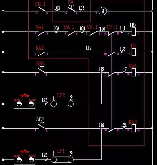
(1) Energy storage loop
Problem: Motors don’t store energy
Processing method: as shown in the figure, the energy storage loop passes through point finite position auxiliary contact S8.1, energy storage knob, motor.
First check that the wiring is not loose. If it is not loose, then check whether the energy storage knob is good. Rotate the knob to the connected state, and use a multimeter to measure the on/off point to see whether the point becomes a closed point.
If can’t energy storage and energy storage limit switches are in good condition, without energy storage condition S8.1 as a normally closed state, such as screening several motor still can’t for this problem, such as the circuit is a direct current (dc), check whether the connection is positive negative corresponding motor is negative, if take the lead to motor reversal, light secondary side of molten core is burned,
If the molten core is large, the motor will start to overload and burn out.
(2) closing circuit
Because of the electrical five, so the closing circuit through the auxiliary contact more, the common auxiliary contact position is ① lower door auxiliary contact (only in the cable room door is closed under the condition of normally open auxiliary contact of the loop can become normally closed state)
Grounding auxiliary contact (only when the grounding knife is in separate state, the normally open auxiliary contact of the loop can become normally closed state)
(3) Disconnecting switch auxiliary contact (normally open auxiliary contact of the loop can change to normally closed state only when the disconnecting switch is closed state)
Energy storage position auxiliary contact (normally open contact of the circuit can change to normally closed state only when the motor is in the state of energy storage)
Therefore, press the closing button SB1 on the diagram, first relay KA1 will be electrically closed, and then the normally open contact of the closing circuit KA1 will change to normally closed state. If it is confirmed that the lower door is closed, the isolation switch is in the closing state, the grounding switch is in the opening state, and the motor has been stored energy.
At this time, the closing coil works electrically, and the switch closing mechanism is touched to close the switch.
Therefore, when we cannot close the gate, first of all, we should judge all the auxiliary contact states (namely, the ground switch state, the isolation switch state, the motor energy storage state, the lower door closing state) from the hardware facilities to the back state to solve the problem, which will get twice the result with half the effort.
(3) brake circuit
As can be seen from the schematic diagram, the circuit is relatively simple, just need to judge the break relay, break coil, break button


Address:No.27, Binhai South 3 road, Yueqing Economic Development Zone, Wenzhou City,Zhejiang Province,China.