You can know every new products be published here, and witness our growth and innovation.
Date:09-01-2026
When it comes to medium-high voltage power cable systems, cable intermediate joints act as one of the most vulnerable links for long-term field operation. A well-made joint does far more than just connect two cable conductors together. It has to handle electric-field stress relief, insulation restoration and solid mechanical protection all at once. It needs to stand up to continuous working voltage, shifting load cycles, humid surroundings and external mechanical impacts day in and day out.
Poor workmanship on intermediate joints will leave hidden defects that you cannot spot from surface inspection. Over time, under combined voltage, current and environmental stress, those tiny flaws will gradually turn into severe line failures. Loose conductor contact brings higher contact resistance and abnormal overheating. Imperfect insulation treatment causes local electric-field concentration, partial discharge and accelerated insulation aging. Water ingress through defective sealing will trigger tree-type discharge inside the joint. Broken shielding structures will mess up internal electric-field distribution. All these issues will weaken cable load-bearing capacity and raise unexpected outage risks.
Three typical weak points frequently pop up during on-site joint fabrication. First off, inaccurate cable stripping dimension. If stripped length is too short, accessories cannot sit in correct mounting position. If stripped too long, more cable core gets exposed to moisture and physical damage. Uneven semi-conductive layer grinding or skewed main-insulation cutting will break uniform electric-field distribution. Many field workers rely purely on personal experience without double-checking dimensions, which passes errors down to follow-up assembly steps.
Second, improper conductor crimping and insulation recovery. Wrong crimping sleeve size, mismatched dies or disordered crimping sequences lead to uneven conductor force distribution. Insufficient crimping creates poor contact and heat generation, while over-crimping damages conductor structure. Sharp burrs and metal chips left after crimping become potential discharge triggers. Rough cleaning, mis-aligned stress-cone installation and inconsistent wrapping thickness will greatly cut down joint withstand-voltage performance.
Third, insufficient sealing-moisture proof and shielding handling. Cable trenches and underground environments stay damp most of the time. Gaps inside sealing compound, uneven heat shrink temperature or displaced cold-shrink parts create micro-channels for water vapor penetration. Loose shield overlap, poor copper-braid connection and unreliable grounding break shielding continuity, inducing arc discharge and local overheating inside the joint. Without intermediate check-ups during construction, concealed defects keep worsening after grid connection.
To mitigate those risks, full-process quality management should be implemented across the whole workflow.
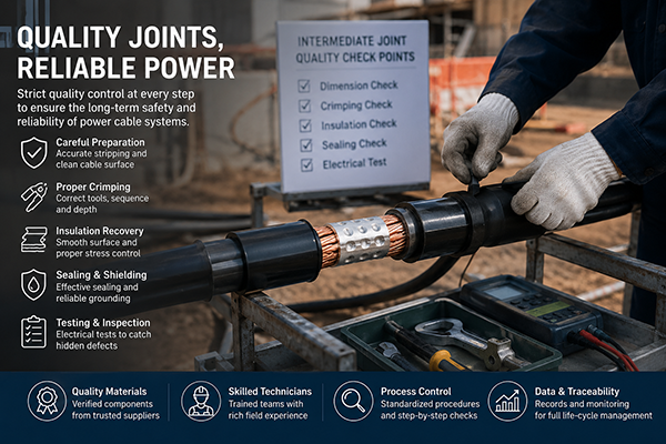
✅ Raw material & working environment management Carry out full check-up for cable accessories, connection sleeves, insulation and sealing materials before installation. Verify model rating, voltage class, cable size and factory certificates. Reject components with cracks, dirt or deformation. Keep job site dry, clean and well-ventilated. Set up temporary shelter for outdoor work to avoid dust, rain and direct sunlight. Clean cable outer surface thoroughly before joint fabrication.
✅ Standardized operation for critical working steps Follow official process specifications, construction drawings and accessory installation manuals strictly. Use dedicated fixtures for cable stripping to avoid accidental insulation scratch. Complete conductor crimping with matched dies, then polish all sharp edges afterwards. Keep main-insulation surface smooth and spot-free during insulation recovery. Calibrate stress-relief position, overlap width and shrink timing for every accessory. Set key-point re-checks to stop construction errors from accumulating.
✅ Inspection & test for hidden sections Since inner joint structure cannot be visually observed, perform point-by-point verification after each key step. Check crimp position, crimp depth, sleeve flatness and conductor insertion depth after conductor crimping. Confirm no scratch, burr or residual semi-conductive substance on main-insulation surface. Take on-site photos for quality records. Once joint assembly finishes, run insulation resistance test, voltage withstand test and partial-discharge test, plus infrared thermal measurement. Discover and fix hidden defects before commissioning.
When construction defects show up on site, handle them according to defect severity. Minor scratches on main-insulation can be polished and cleaned on-site. Smooth crimping burrs before insulation recovery. Repair sealing gaps with supplementary sealing work. For severe defects that threaten electrical performance, do not hesitate to disassemble and remake the joint completely; never put flawed joints into service.
After quality control measures get fully implemented, human-operation errors drop significantly. Standardized checklists help field staff finish dimension setting, cable stripping and accessory assembly properly. Material incoming inspection and site-environment control reduce accessory contamination and mismatching issues. Re-check mechanisms catch hidden risks such as bad crimping and poor shield connection. Final acceptance depends on test data rather than simple visual judgment.
Post-operation monitoring data offers another important feedback source. Infrared temperature reading detects abnormal joint temperature rise under loaded conditions. Partial-discharge monitoring captures insulation voids, tip discharge and moisture aging risks. Track insulation resistance, grounding current and sheath circulating current. Build dedicated joint operation files that combine construction records, test reports and patrol data. Use these archives to adjust inspection frequency and optimize future fabrication procedures.
Long-term quality improvement also needs three more pillars.
1.Upgrade practical skill training for field technicians. Combine theoretical learning with real-defect sample demonstration. Assess workers through simulated practice and finished-product inspection, not only written exams. Normalize on-job training to cut down arbitrary field operations.
2.Bring intelligent monitoring tools into daily management. Infrared thermometry, on-line partial-discharge monitoring, sheath circulating-current monitoring and digital patrol support early risk alert. AI algorithms analyze operation data to rank equipment risk levels. Realize traceability from construction phase to whole-cycle operation status.
3.Dynamic archive management for joint O&M. Build digital electronic files covering construction, acceptance, grid-connection, patrol and maintenance. Record cable specification, installation location, accessory supplier, operator, key fabrication parameters and test results. Automatically log abnormal patrol findings. Adjust inspection strategies for aged joints with frequent faults based on historical data, and achieve closed-loop full-life-cycle management.
All in all, intermediate joint quality directly decides the reliability of power cable lines. Quality improvement cannot rely merely on post-fault repair. We need closed-loop control covering material acceptance, on-site execution, hidden-point check-up, type test and post-commission data feedback. Together with technician competence building, intelligent monitoring and digital archive system, we can push cable-joint quality management toward refined, standardized and dynamic control mode.


Address:No.27, Binhai South 3 road, Yueqing Economic Development Zone, Wenzhou City,Zhejiang Province,China.