High-voltage switchgear refers to electrical products used for on-off, control or protection in power generation, transmission, distribution, power conversion and consumption of the power system. The voltage level is between 3.6kV and 550kV. It mainly includes high-voltage circuit breakers and high-voltage isolation. Switches and grounding switches, high-voltage load switches, high-voltage automatic coincidence and sectioning devices, high-voltage operating mechanisms, high-voltage explosion-proof power distribution devices, and high-voltage switch cabinets. The high-voltage switch manufacturing industry is an important part of the power transmission and transformation equipment manufacturing industry and occupies a very important position in the entire power industry. Function: The high-voltage switchgear has the functions of overhead incoming and outgoing wires, cable incoming and outgoing wires, and bus connection.
Application: Mainly suitable for various places such as power plants, substations, power system substations, petrochemicals, metallurgical steel rolling, light industry and textiles, factories and mining enterprises and residential communities, high-rise buildings, etc.Composition: The switchgear shall meet the relevant requirements of the “AC metal-enclosed switchgear” standard. It is composed of a cabinet and a circuit breaker. The cabinet is composed of a shell, electrical components (including insulators), various mechanisms, secondary terminals and Connection and other components.
Five defenses:
1. Prevent closing under load: After the vacuum circuit breaker trolley in the high-voltage switch cabinet is closed at the test position, the trolley circuit breaker cannot enter the working position.
2. Prevent closing with grounding wire: When the grounding knife in the high-voltage switch cabinet is in the closed position, the trolley circuit breaker cannot be closed.
3. Prevent accidental entry into the live interval: When the vacuum circuit breaker in the high-voltage switch cabinet is closing, the back door of the panel is locked with the machine on the grounding knife and the cabinet door.
4. Prevent live grounding: The vacuum circuit breaker in the high-voltage switchgear is closed when it is working, and the grounding knife cannot be put in.
5. Prevent the load-carrying switch: the vacuum circuit breaker in the high-voltage switchgear cannot exit the working position of the trolley circuit breaker when it is in operation.
Structure and composition
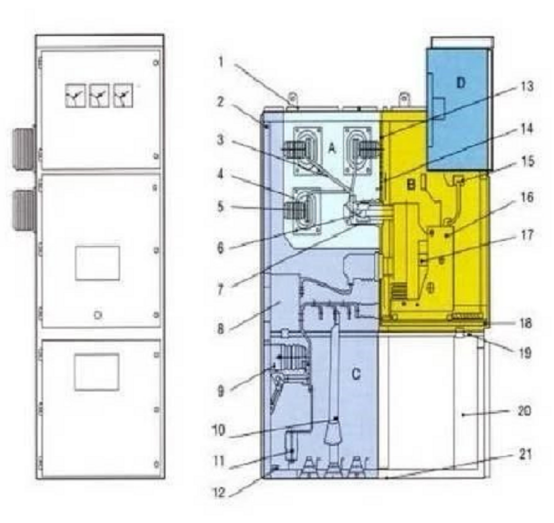
It is mainly composed of cabinet, high-voltage vacuum circuit breaker, energy storage mechanism, trolley, grounding knife switch and comprehensive protector.The following is an example of a high-voltage switchgear, to show you the detailed internal structure
A: Bus room
B: (circuit breaker) handcart room
C: Cable room
D: Relay instrument room
1. Pressure relief device
2. Shell
3. Branch bus
4. Bus bushing
5. Main bus
6. Static contact device
7. Static contact box
8. Current transformer
9. Grounding switch
10. Cable
11. Avoidance
12. Press the ground bus
13. Removable partition
14.Partition (trap)
15. Secondary plug
16. Circuit breaker handcart
17. Heating dehumidifier
18. Withdrawable partition
19. Grounding switch operating mechanism
20. Control the wire trough
21. Bottom plate
①Cabinet
It is formed by pressing iron plates and is a closed structure, with instrument room, trolley room, cable room, busbar room, etc., separated by iron plates, as shown in Figure 1. The instrument room is equipped with integrated protectors, ammeters, voltmeters and other devices; the trolley room is equipped with trolleys and high-voltage vacuum circuit breakers; the busbar room is equipped with three-phase busbars; the cable room is used to connect power cables to the outside.
②High voltage vacuum circuit breaker
The so-called high-voltage vacuum circuit breaker is to install its main contacts in a closed vacuum chamber. When the contacts are on or off, the arc has no gas-supported combustion, which will not burn out and is durable. At the same time, insulating materials are used as the base to improve the vacuum switch. It is called a high-voltage vacuum circuit breaker because of its insulation performance.
③Car mechanism
Install the high-voltage vacuum circuit breaker on the trolley and move with the trolley. When the handle is shaken clockwise, the trolley enters the cabinet and inserts the vacuum circuit breaker into the high-voltage circuit; when the handle is shaken counterclockwise, the trolley exits the cabinet and drives the vacuum circuit breaker Draw out the high-voltage circuit, as shown in Figure 2.
④ Energy storage organization
A small motor drives the spring to store energy, and the vacuum circuit breaker is closed by using the spring to release the kinetic energy.
⑤Ground knife switch
It is a knife switch that acts on safety interlock. The high-voltage cabinet door can only be opened when the grounding knife switch is closed. Otherwise, the high-voltage cabinet door cannot be opened when the grounding knife switch is not closed, which plays a role of safety interlock protection.
⑥Comprehensive protector
It is a microcomputer protector composed of a microprocessor, display screen, keys and peripheral circuits. Used to replace the original overcurrent, overvoltage, time and other relay protection circuits. Input signal: current transformer, voltage transformer, zero-sequence current transformer, switch value and other signals; the keyboard can be used to set current value, voltage value, quick-break time, start-up time and other data; the display screen can display real-time data and participate in control, execution Protection action.
Classification
(1) According to the main wiring form of the switch cabinet, it can be divided into bridge wiring switch cabinet, single bus switch cabinet, double bus switch cabinet, single bus section switch cabinet, double bus with bypass bus switch cabinet and single bus section belt Bypass bus switch cabinet.
(2) According to the installation method of the circuit breaker, it can be divided into a fixed switch cabinet and a removable (handcart type) switch cabinet.
(3) According to the cabinet structure, it can be divided into metal-enclosed compartmental switchgear, metal-enclosed armored switchgear, and metal-enclosed box-type fixed switchgear.
(4) According to the installation position of the circuit breaker handcart, it can be divided into floor-mounted switchgear and middle-mounted switchgear.
(5) According to the different insulation medium inside the switchgear, it can be divided into air insulated switchgear and SF6 gas insulated switchgear.
The main technical parameters
1. Rated voltage, rated current, rated frequency, rated power frequency withstand voltage, rated lightning impulse withstand voltage;
2. The circuit breaker has moderate rated breaking current, rated closing peak current, rated short-time withstand current, and rated peak withstand current;
3. The rated short-time withstand current and the rated peak withstand current of the grounding switch;
4 Operating mechanism opening and closing coil rated voltage, DC resistance, power, rated voltage and power of energy storage motor;
5. The cabinet protection level and the national standard number that it complies with.
Power transmission procedure
1. Close all the back doors and the back cover, and lock them. Only when the grounding switch is in the closed position can the back door be closed
2. Insert the operating handle of the grounding switch into the hexagonal hole on the lower right side of the middle door, and turn it counterclockwise to make the grounding switch in the open position. The interlocking plate at the operating hole will automatically bounce back to cover the operating hole, and the cabinet lower door will be locked.
3. Push the service trolley to position it, push the trolley into the cabinet to position it in the isolated position, manually insert the secondary plug, and close the door of the trolley compartment.
4. Insert the handle of the circuit breaker handcart into the socket of the handle, and turn the handle clockwise for about 20 turns. Remove the handle when the handle is obviously blocked and there is a clicking sound. At this time, the handcart is in the working position, and the handle is inserted twice. Is locked, the main circuit of the circuit breaker trolley is connected, and the relevant signals are checked.
5. The operation is to close on the meter board, and the switch-off switch makes the circuit breaker close and send power. At the same time, the green light on the dashboard is off and the red light is on, and the closing is successful.
Power failure operation procedure
1. Operate the instrument panel to close, and the opening changeover switch makes the circuit breaker in the opening and shelving, at the same time the red light on the instrument panel is off and the green light is on, the opening is successful.
2. Insert the handle of the circuit breaker handcart into the socket of the handle, and turn the handle clockwise for about 20 turns. Remove the handle when the handle is obviously blocked and there is a clicking sound. At this time, the handcart is in the test position. Unlock, open the door of the handcart room, manually disengage the secondary plug, and disconnect the main circuit of the handcart.
3. Push the service trolley to lock it, pull out the trolley to the service trolley, and drive the service trolley.
4. Observe the charged display or check if it is not charged before continuing to operate.
5. Insert the operating handle of the grounding switch into the hexagonal hole on the lower right side of the middle door, and turn it clockwise to make the grounding switch in the closed position. After confirming that the grounding switch is indeed closed, open the cabinet door and the maintenance personnel can enter the maintenance. Overhaul.
Judgment and treatment of closing faultClosing faults can be divided into electrical faults and mechanical faults. There are two kinds of closing methods: manual and electric. The failure to close manually is generally a mechanical failure. Manual closing can be done, but electric failure is an electrical fault.
1. Protection action
Before the switch is powered on, the circuit has a fault protection circuit to make the anti-trip relay function. The switch trips immediately after closing. Even if the switch is still in the closed position, the switch will not be closed again and jump continuously.
2. Protection failure
Now the five-prevention function is set in the high-voltage cabinet, and it is required that the switch cannot be closed when it is not in the operating position or the test position. That is, if the position switch is not closed, the motor cannot be closed. This kind of fault is often encountered during the closing process. At this time, the running position lamp or the test position lamp does not light up. Move the switch trolley slightly to close the limit switch to send power. If the offset distance of the limit switch is too large, it should be adjusted. When the position switch in the JYN type high voltage cabinet cannot be moved outward, a V-shaped piece can be installed to ensure the reliable closing of the limit switch.
3. Electrical cascading failure
In the high-voltage system, some electrical interlocks are set up for the reliable operation of the system. For example, in a single-bus section system with two incoming power lines, it is required that only two of the three switches, the two incoming line cabinet and the bus joint cabinet, can be combined. If all three are closed, there will be a danger of reverse power transmission. And the short-circuit parameters change, and the parallel operation short-circuit current increases. The form of the chain circuit is shown in Figure 4. The incoming cabinet interlock circuit is connected in series with the normally closed contacts of the bus joint cabinet, and the incoming cabinet can be closed when the bus joint cabinet is open.
The interlocking circuit of the bus joint cabinet is connected in parallel with one normally open and one normally closed of the two incoming cabinets respectively. In this way, it can be ensured that the bus joint cabinet can only transmit power when one of the two incoming cabinets is closed and the other is opened. When the high-voltage cabinet cannot be closed electrically, first consider whether there is an electrical interlock, and cannot blindly use manual closing. Electrical cascading failures are generally improper operation and cannot meet the closing requirements. For example, although the incoming bus coupler is one opening and one closing, the handcart in the opening cabinet is pulled out and the plug is not plugged in. If the interlock circuit fails, you can use a multimeter to check the fault location.
Using red and green lights to judge the auxiliary switch failure is simple and convenient, but not very reliable. It can be checked and confirmed with a multimeter. The method of overhauling the auxiliary switch is to adjust the angle of the fixed flange and adjust the length of the auxiliary switch connecting rod.
4. Open circuit fault of control circuit
In the control loop, the control switch is damaged, the circuit is disconnected, etc., so that the closing coil cannot be energized. At this time, there is no sound of action of the closing coil. There is no voltage across the measuring coil. The inspection method is to check the open circuit point with a multimeter.
5. Failure of closing coil
Burning of the closing coil is a short-circuit fault. At this time, peculiar smell, smoke, short fuse, etc. occur. The closing coil is designed for short-time work, and the energizing time cannot be too long. After the closing failure, the reason should be found in time, and the compound brake should not be reversed multiple times. Especially the closing coil of the CD type electromagnetic operating mechanism is easy to burn out due to the large passing current.
The power test method is often used when repairing the fault that the high-voltage cabinet cannot be closed. This method can eliminate line faults (except for transformer temperature and gas faults), electrical cascading faults, and limit switch faults. The fault location can basically be determined inside the handcart. Therefore, in the emergency treatment, you can use the test location to test power transmission, and replace the standby handcart power transmission method for processing. This can get twice the result with half the effort and can reduce the power outage time.