You can know every new products be published here, and witness our growth and innovation.
Date:09-10-2021
1)110 ~ 220kV plug cable terminal
In the application of GIS combined appliances, the transformer or GIS is sometimes led out from the transformer or GIS directly by high-voltage cable instead of the traditional bushing.There are many types of high-voltage cable equipment terminals, the selection of appropriate GIS, transformer and cable installation, test and future operation and maintenance is very important.
1.1 Type of device terminal
The cable feeder on high voltage equipment is used for mechanical fixation of cable feeder and electrical transition connection with transformer or GIS combined appliance body.The epoxy sleeve at the cable terminal effectively prevents insulation oil or SF6 gas from infiltrating into the cable body.In order to solve the electrical insulation problem of cable terminal in epoxy resin casing cavity, the traditional solution is to fill the casing cavity with oil or SF6 gas. The equipment terminal of this kind of high-voltage cable is called oil-filled (or inflatable) type, also known as wet type.Its charging method is less used, generally filled with oil.
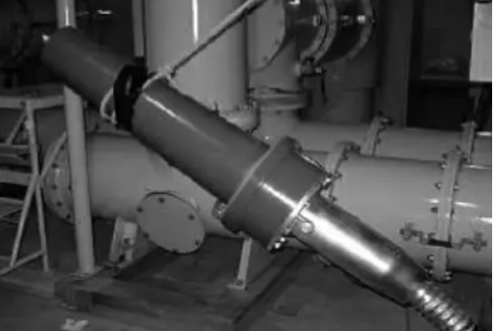
The terminal of oil-filled wet equipment shall complete the electrical and mechanical connection and installation with the cable inlet warehouse on site. In the field test and installation work, the personnel of the high-pressure equipment manufacturer shall cooperate to complete the charging and releasing of air (oil) and other work of the cable inlet warehouse, and the working procedure is quite troublesome.Some oil filling terminals are attached with a respirator (with a transformer-like oil pillow function);Some also need to use vacuum way to realize the epoxy resin casing oil injection, very inconvenient.The figure below shows the oil-filled 110kV cable terminal to be assembled on the GIS integrated appliance.
Another type of high voltage cable terminal by optimizing the structure design, realized the stress cone and cable terminal head epoxy resin for the inner surface of casing no clearance contact and ideal uniform distribution of power line, without casing to epoxy resin filling oil (gas) well solve the problem of the electrical insulation sleeve cavity, this kind of terminal called dry terminal equipment.
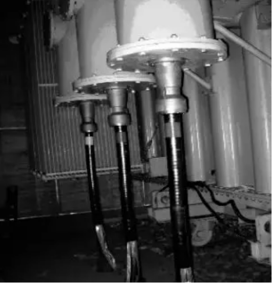
The dry high voltage cable terminal is oil-free and fully enclosed, so the position of the cable terminal is not restricted, and the connection between the cable and GIS combined appliance or transformer can be flexibly realized in different directions according to the needs of the site.
The following figure shows a dry cable terminal assembled from the lower part of the cable inlet bin located on the side of the transformer.
According to the assembly characteristics of dry high voltage cable terminals, they can be divided into three categories.
The first type is the conventional type, that is, epoxy resin casing and cable, stress cone integral installation and test.
The installation procedure in the field is almost the same as the wet terminal, except that the casing is not filled with oil (gas).
In the field test and installation work, it still needs the personnel of the high voltage equipment manufacturer to cooperate with the field to complete the charging and discharging (oil) work of the cable inlet warehouse, and the work procedure and cross operation of the overall installation are quite cumbersome.
The second type is plug-in type, in which the epoxy resin sleeve of the cable terminal can be installed separately from the cable and stress cone, but cannot be tested separately.
A spring locking device is installed on the conductive rod crimped to the cable core. When the cable end is inserted into the epoxy sleeve in place, the spring locking device automatically pops out and locks the cable end into the epoxy sleeve to ensure that it does not slip off.
Once inserted, the cable end of this type of cable cannot be pulled out again.
The installation procedure of plug-in cable terminal is basically the same as that of the first class. For example, for GIS combined appliances, the epoxy resin sleeve can be installed on the CABLE inlet bin of GIS in advance in the factory. The epoxy resin sleeve can completely isolate the SF6 gas in the cable inlet bin from the outside, reducing the on-site cooperation workload of the manufacturer.
However, when problems occur in the cable test and need to be treated, it is still necessary to charge and discharge the gas in the cable into the cable bin.
In addition, when plug-in cable terminals are used in transformers, their installation and test work is the same as class 1 conventional cable terminals.
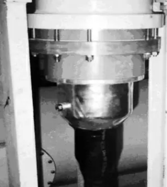
The following figure shows a plug-in cable terminal plugged into a GIS appliance.
The third type is plug and pull cable terminal, the casing, cable, stress cone can be installed separately, also can be separately tested;
The cable head can be inserted or pulled out.
Its structure is the most simple, the most convenient installation.
Pluggable cable terminals are also divided into reusable and non-reusable two types.
A cable terminal that can be reassembled by removing the parts of the cable end plug is called a reusable pluggable cable terminal; otherwise, it is a non-reusable pluggable cable terminal.
The field installation of plug – in cable terminal has the following characteristics:
(1) Epoxy resin casing can be installed and connected to GIS or transformer in advance, and can be tested with GIS or transformer at the same time;
(2) just complete the assembly of the cable head part on site;
(3) the cable can be tested separately with the test sleeve, without the cooperation of equipment manufacturers;
(4) After passing the test, insert the cable into the epoxy resin casing, and complete the installation after installing the grounding wire.
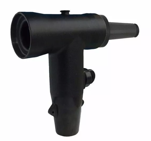
The following figure shows the schematic diagram of a typical pluggable terminal.
The plug – in cable terminal and GIS box can be used to form the “T – type” connector of the cable.
Figure 5 shows the cable “T” joint installed in the tunnel, which can realize one in and two out of the cable.
It can flexibly realize the following functions: (1) When the outgoing line needs to be added in the transformation of the old substation, the “T” type connection can avoid increasing the GIS interval;
(2) In the middle section of the cable line, the use of “T” type wiring can easily supply power to new users;
③ When there is a long-term outlet line but not yet meet the conditions, can not install the outlet line and use the “T” type wiring way reserved outlet position and install a special insulation plug, the main line can be put into operation;
④ When two cables are laid in parallel from the substation for a long time, it is more economical to choose a single cable outlet and use “T” connection mode for power supply at the branch point.
In addition, when one of the three operating cables connected by “T” fails, the faulty cable can be pulled out and the other two cables can continue to run after installing special insulation plug.
1.2 Performance comparison and selection principle of high voltage cable equipment terminal
All kinds of high voltage cable terminals in the electrical performance of the strict test, can meet the requirements of the national standard IEC60859, in the installation, test, operation and maintenance and fault handling and other aspects of all kinds of cable terminals have different characteristics.
The cable terminal must have the same electrical performance, working temperature and service life as the cable in the selection.
Cable terminal structure should ensure good electric field distribution and prevent insulation shrinkage measures.
In principle, it has the following aspects:
(1) Electrical performance.
The main consideration is whether the electric field distribution of cable accessories is reasonable, whether the measures to improve the electric field distribution are appropriate, the electrical strength of materials, dielectric loss and insulation margin of products, etc.
At the same time, it is necessary to consider the stability of electrical properties, including the chemical and physical properties and structural stability of cable accessory materials.
For example, whether the performance of stress control materials is stable, whether the stress cone is easy to deform, the influence of cable insulation retraction on the electric field distribution of cable accessories and preventive measures, the compatibility of various materials, the stability of interface properties, etc.
In addition, the thermal performance of cable accessories should also be considered, such as dielectric loss, contact resistance of conductor connection and its stability, heat conduction release, thermal expansion and contraction on the electrical and mechanical properties of each component.
(2) Sealing performance.
Sealing moisture-proof performance directly affects the electrical performance and service life of cable accessories.
Terminal sealing structure is reliable and stable.
(3) Mechanical properties.
The terminal should have enough bending and shock resistance.
(4) Process performance.
The process performance is an important condition for the design and selection of cable accessories. The installation process should be as simple as possible, convenient for site construction, and the construction period should be short.
High quality products are not dependent on the site environment requirements and installation workers’ technical level;
Installation quality easy to control, reliable quality and so on.
The installation of cable terminals can be completed independently without the oil and air discharge coordination of transformer or GIS manufacturers, and the installation quality can be easily guaranteed.
(5) Suitable for the requirements of the project.
Many types of cable accessories have their own characteristics, the selection of cable accessories should be decided according to the actual use requirements.
(6) Manufacturer’s quality assurance system.
When the prefabricated cable accessories leave the factory, the manufacturer provides parts and materials such as rubber prefabricated parts, prefabricated stress cones, porcelain sleeves, shells and impregnators, which are assembled into integral terminals or joints during on-site installation.
The manufacturing quality and installation process of each component directly affect the quality of cable accessories.
This quality assurance program should include at least the following: ① Factory test should be carried out strictly on key parts (such as rubber stress cone, GIS epoxy resin sleeve, impregnation agent, etc.).
Check carefully whether the test and measurement equipment is reliable, test methods are effective, test personnel are well trained and test records are complete;
(2) Whether the installation and construction personnel dispatched by the manufacturer are strictly trained and have enough construction experience;
(3) Whether the coordination between different departments of the manufacturer is good;
(4) Previous sales and operation records.
In the selection of cable terminal, the test and maintenance after cable assembly and the test and maintenance of cable fault should be fully considered. It should be easy to realize the separate test and maintenance of cable, transformer and GIS without interfering with each other.
Of course, the interchangeability, reusability, maintenance-free, compact structure and product price of cable terminals are also important factors that should be considered in the selection.
Two, 10 ~ 35kV plug cable terminal
2.1 Type of device terminal
There are many types of cable plug heads, which are generally divided into American and European models.
The main function of the cable plug is to connect the single-phase or three-phase cable with switch cabinet, transformer, ring network cabinet, cable tap box and other electrical equipment.
Constitute the plug before and after at least one plug, plug before and after the plug ontology to the T tube structure, T tube for perpendicular horizontal hole and vertical hole, plug, plug before and after the plug before and after the plug horizontal sequence splice together, T the vertical hole casing with wire terminals, the top of the line pressing terminal is equipped with pressure,
A connecting device is arranged in the horizontal through hole of the front plug and the back plug, and the connecting device is connected with the wire pressing port, and the wire pressing terminal is connected with the cable.
Connectors and front and rear plugs are factory prefabricated, flexible in and out line, small volume, compact structure, simple installation process, high safety, can be used in switch cabinet and cable branch line and other places, suitable for indoor or outdoor installation.
Cable plug head has more nicknames, elbow joint, T joint, separable cable terminal and so on a series of names.
Generally, the voltage grade should be concentrated in 10kV and 35kV, and the application model is usually divided into European and American types.
The main differences between American and European busbar and cable head arrangement is different, American horizontal arrangement, European vertical arrangement.
The figure below is European.
European cable plug head is connected by shielding bolt type;
It is suitable for ring switch cabinet, cable distribution box, box type substation (cross-linked power cable) inlet and outlet terminal, and double through insulation pipe thread connection.
The outer layer has a shielding semi-conductive layer, which can be touched to ensure personal safety;
The unique stress cone structure effectively disperses the electric field stress and solves the cable shielding layer cut;
Electric field stress problem;
Expansibility, flexible disassembly and assembly, can complete the “T” type cable connection;
Full airtight, full insulation, full protection, maintenance-free, anti-flooding, anti-pollution.


Address:No.27, Binhai South 3 road, Yueqing Economic Development Zone, Wenzhou City,Zhejiang Province,China.